


Fiber Installation
A suitable sensing cable is installed along the monitored asset or infrastructure route.

Continuous, real-time temperature monitoring and thermal trend analysis for critical assets and infrastructure.
REQUEST A QUOTEFOTAS INTEGRITY is a high-resolution Distributed Temperature Sensing platform engineered for continuous, long-range asset integrity monitoring.
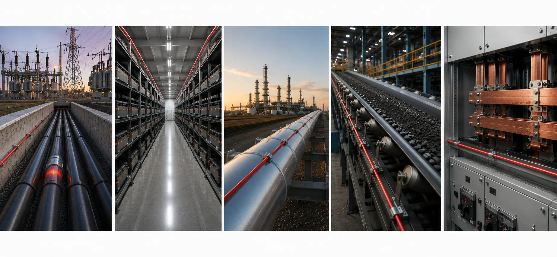
The system converts a passive fiber optic sensing cable into thousands of distributed temperature measuring points along power cables, pipelines, conveyors, battery systems and electrical infrastructure.
Instead of relying only on isolated temperature readings, INTEGRITY provides a continuous thermal profile that helps engineers identify hot spots, changing operating conditions and deviations from established thermal behavior.
This thermal information supports condition-based and predictive maintenance programs without replacing engineering assessment or asset-specific diagnostic procedures.
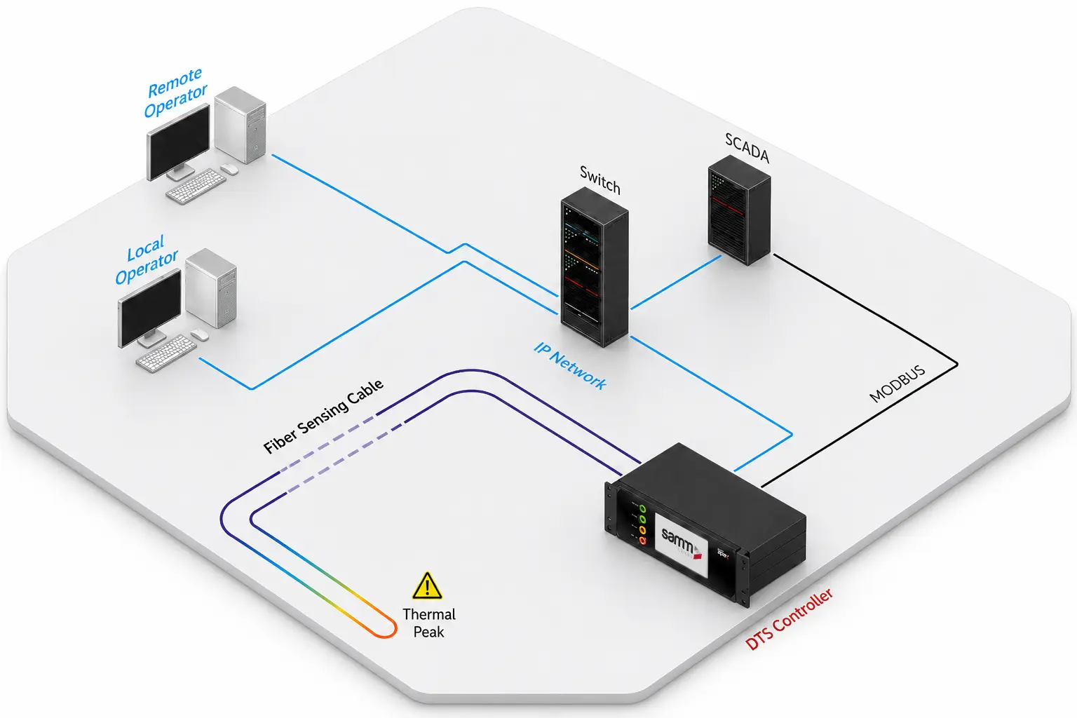
A suitable sensing cable is installed along the monitored asset or infrastructure route.
The controller sends laser pulses through the fiber and analyzes temperature-dependent Raman backscatter.
The system calculates temperature and position information along the full sensing route.
Current temperature behavior is compared with configured limits, zones and historical operating patterns.
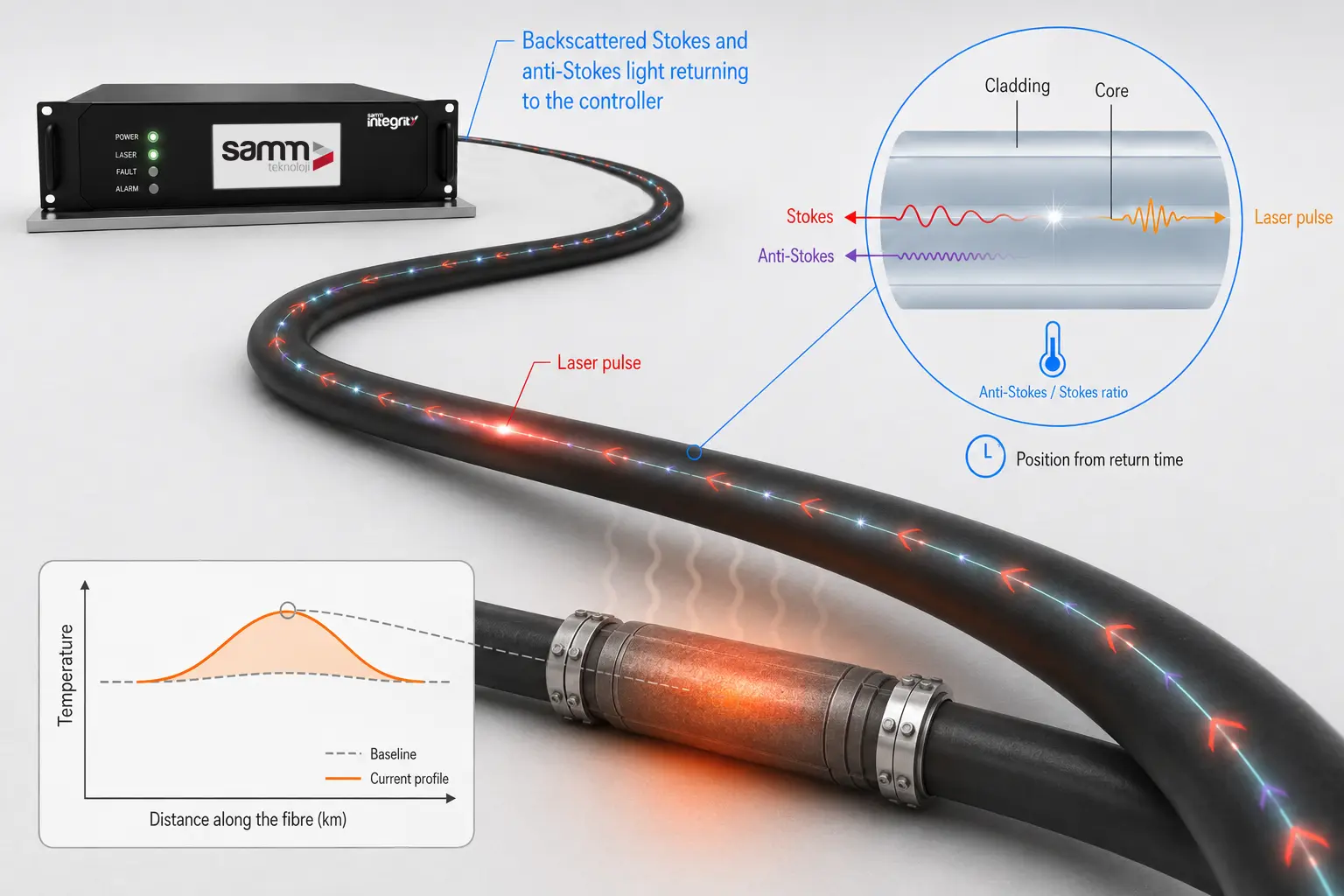
Learn how Raman backscatter and time-of-flight analysis produce spatially resolved temperature information.
Selected configurations provide nominal sensing ranges of 10, 20, 30 or 40 km for long and linear assets.
Two, four, eight and 16-channel architectures support multiple assets, routes or monitoring zones.
Distributed measurements provide detailed temperature information for baseline, trend and operational analysis.
Selected configurations support localized thermal anomaly identification under specified installation and operating conditions.
Final sensing distance, spatial resolution, temperature accuracy and localization performance must be confirmed in the applicable datasheet and project design.
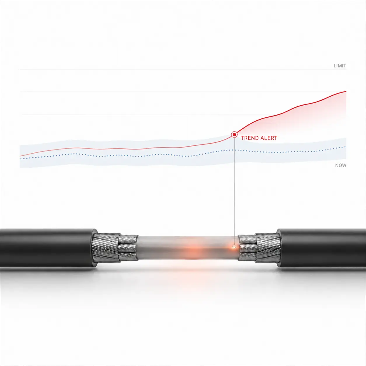
Establish thermal baselines and alert personnel when temperature behavior deviates from its expected or historical pattern.
A deviation indicates that the asset requires investigation; it does not by itself establish a final fault diagnosis.
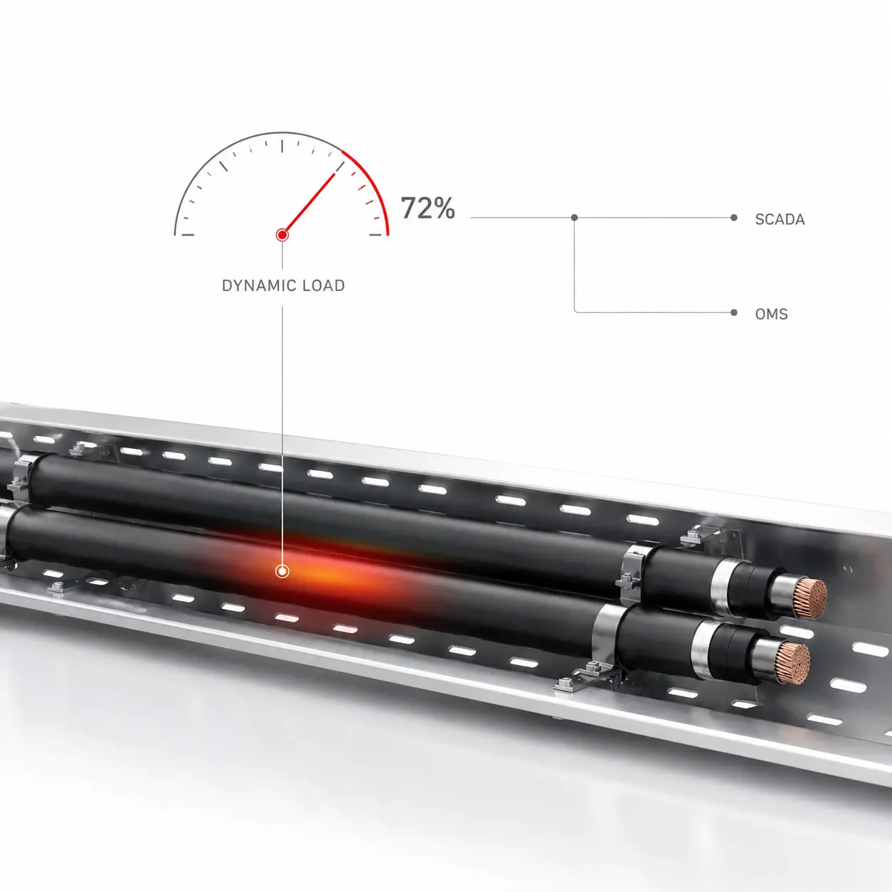
Transfer real-time thermal information to SCADA or operational platforms to support informed load-management decisions.
Dynamic rating functions require the appropriate engineering model, asset data and approved system architecture.
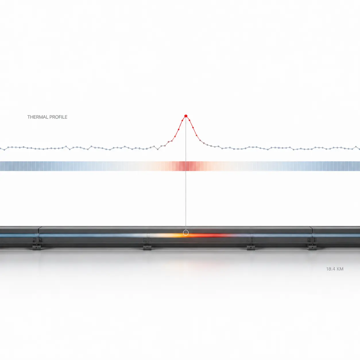
Display longitudinal temperature profiles, customized thermal maps, alarm zones and historical trends through the FOTAS software interface.
Engineers gain a continuous view across thousands of distributed measuring locations.
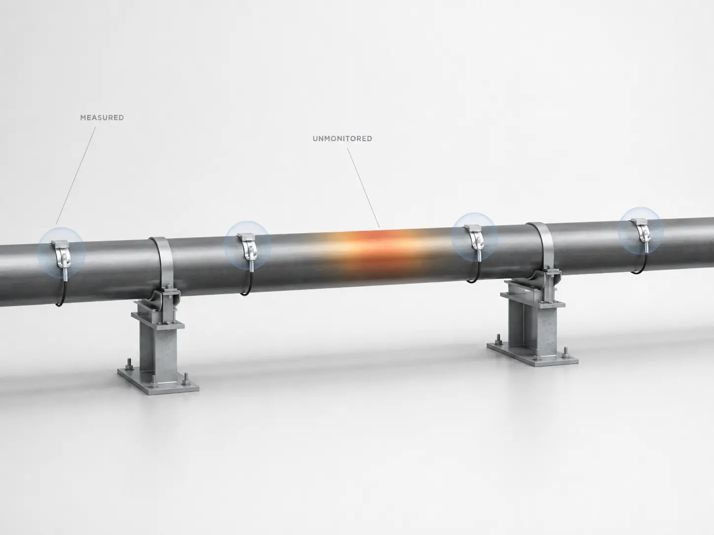
Point sensors measure temperature only at selected physical locations.
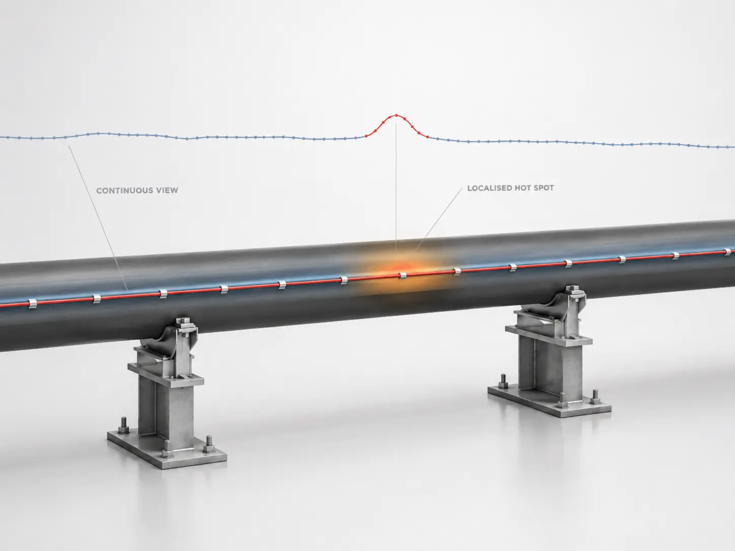
The sensing fiber provides spatially resolved temperature information across the installed route.
Monitor thermal behavior across the complete installed fiber route rather than only selected sensor locations.
Evaluate temperature development over time instead of relying only on fixed high-temperature alarms.
Identify where abnormal temperature behavior is occurring along extended assets and infrastructure routes.
Use measured thermal data to prioritize inspections and maintenance activities according to asset behavior.
The fiber sensing cable requires no electrical power or powered electronic sensors along the monitored route.
Optical sensing is unaffected by electromagnetic and radio-frequency interference.
Continuous fiber sensing reduces dependence on numerous individual field temperature sensors.
Expand monitoring through additional channels, controllers or extended project architecture.
FOTAS INTEGRITY is designed for integration into complex industrial, utility and infrastructure environments.
Thermal profiles, alarm information and selected operating data can be exchanged with supervisory and asset-management platforms according to the approved project architecture.
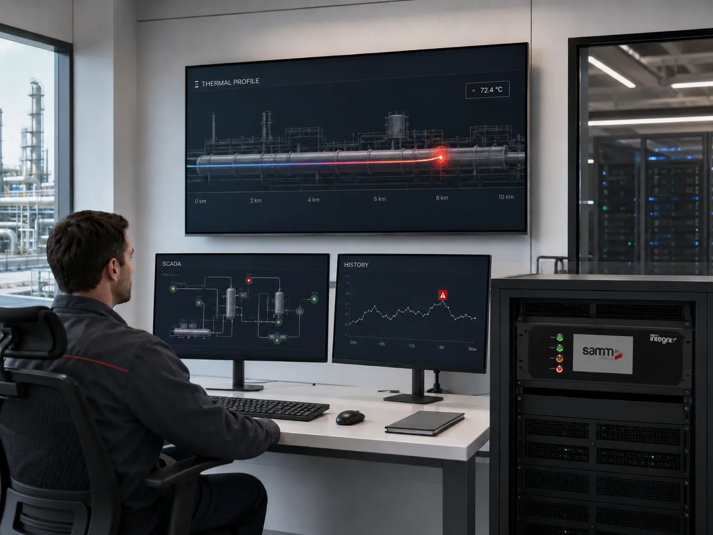
The sensing cable is passive. Controllers, servers, network equipment and supervisory platforms require appropriate power and environmental protection.
The appropriate configuration depends on sensing distance, number of monitored assets, channel architecture, temperature performance, integration requirements and project expansion plans.
Discuss the monitored asset, sensing distance, channel architecture, thermal behavior, integration requirements and maintenance objectives with the FOTAS engineering team.