


Transmission Capacity
Fiber optic cable carries dramatically more data than a copper conductor of comparable size.

FOTAS is a fiber optic distributed acoustic sensor. Understanding this system is only possible by understanding the technologies underlying it.
EXPLORE THE TECHNOLOGY GUIDEDistributed Acoustic Sensing (DAS) technology uses fiber optic cables as sensors to detect acoustic signals. FOTAS combines this technology with lasers, fiber optic engineering and artificial intelligence.
Artificial intelligence helps analyze and interpret the large amounts of data collected by DAS. This makes the system effective in areas such as security and infrastructure monitoring.
The sections below explain how the technology works, starting from the optical fiber itself and continuing through lasers, distributed acoustic sensing and optical time domain reflectometry.
Fiber optics is a sub-field of optics. While optics is the field of light in general, fiber optics is concerned with optical phenomena inside glass fibers only. "Fiber" means thread, so fiber optics refers to the glass threads that allow light to pass through them.
Most telecommunication infrastructure today is based on fiber optic cables. They are the descendants of copper electrical cables — but if electrical cables already existed, why are fiber optic cables used instead?
Earlier standard telecommunication cables were made of copper or other conductive metals. These cables carry electrons from one end to the other, and with the help of other devices this current carries valuable data. Former telephone lines, and then internet lines, were built from this type of cable.
As transferred data volumes grew, current-based cables began to fall short. In 1990 there were roughly 2.6 million internet users; by 2016 that number had reached 3.406 billion. Conventional electrical cables could not handle this demand, and fiber optics took their place.
Fiber optic cables can transmit far more data than copper cables — the difference is approximately on the order of 10 to 1000 times. Capacity puts fiber optics ahead, but the advantages do not stop there.
Fiber optic cable carries dramatically more data than a copper conductor of comparable size.
Optical transmission preserves signal quality over far longer distances before amplification is required.
Data is carried by photons travelling through the glass core, not by electrons in a metal conductor.
Light and durable cables are unaffected by electromagnetic interference along outdoor routes.
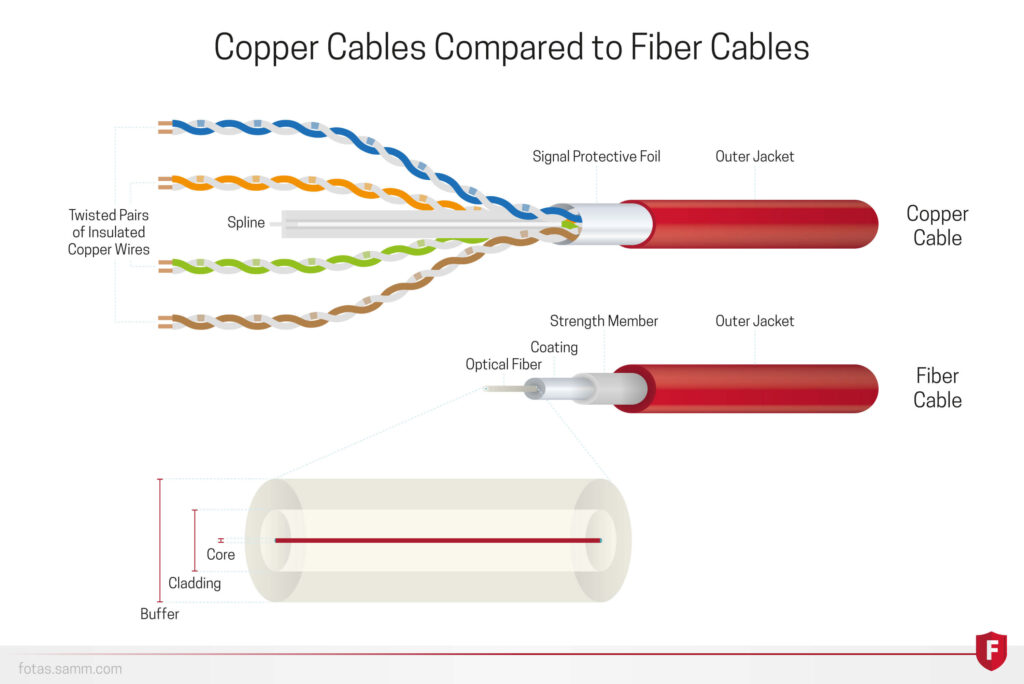
The main component of a fiber optic cable is the optical fiber itself. Optical fibers are made of glass or similar materials, and their purpose is to carry light — so the material must be transparent. The light travelling in the cable is generated by laser devices.
Beyond transparency, the material should be durable, flexible, inexpensive and easy to produce. Glass is surprisingly flexible at 9 micrometers in diameter, and humanity has thousands of years of industrial and craft experience with it. A chunk of glass is drawn from height and processed until it becomes thinner and thinner, until the core reaches roughly 9 micrometers.
A fiber optic cable does not consist of the glass core alone. Light propagating through an unprotected core would scatter in random directions, so it needs a wave-guide and protective layers to reach the target location with minimum loss.
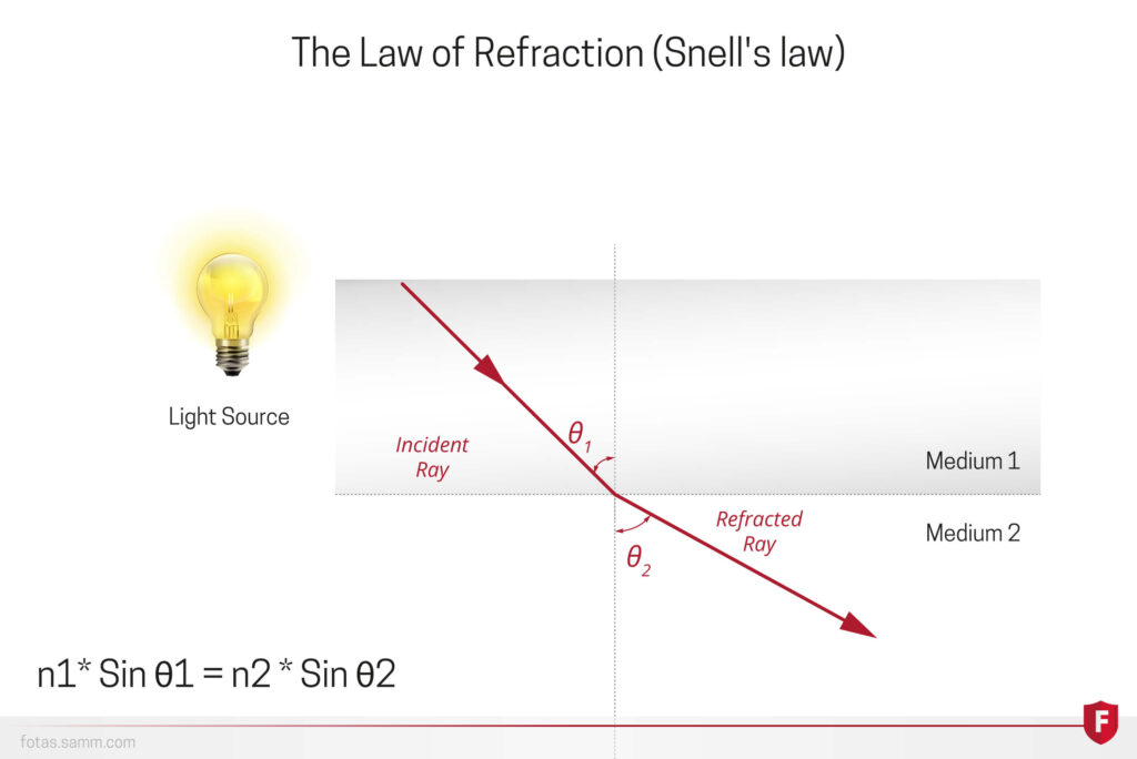
Light travels inside the core and bounces off the fiber walls as it goes. Fiber optic cables are designed so that light rays cannot propagate outwards — nevertheless, some of them do escape. This phenomenon is called optical loss.
The physical law that makes light bounce and stay inside the cable is Snell's Law. When light remains inside the cable without loss while bouncing, the phenomenon is called Total Internal Reflection.
The word laser is an acronym for Light Amplification by Stimulated Emission of Radiation. DAS systems and many other systems rely on laser technology. The FOTAS system uses laser light to obtain intrusion data: laser light travels across the fiber optic cable and scatters inside it, and the scattered light is collected by the OTDR unit.
A laser may look like an ordinary light source, but it is far from it. Laser light is collimated, coherent and polarized — three properties that make Phase-OTDR and FOTAS possible.
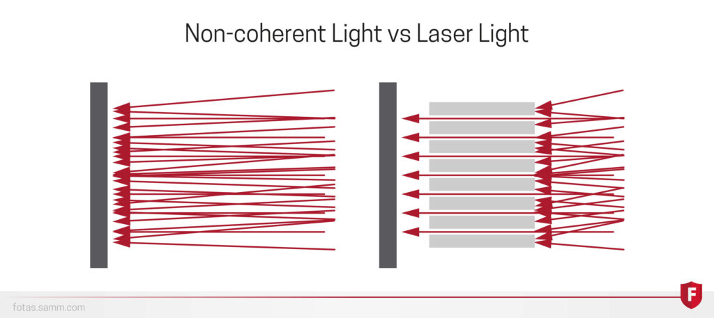
All laser rays are parallel and unidirectional. They travel in the same direction without crossing, so almost no power is lost on the way to the target location.
Divergence still exists, but it is minuscule compared with a bulb or LED — which is exactly what makes long sensing distances possible.
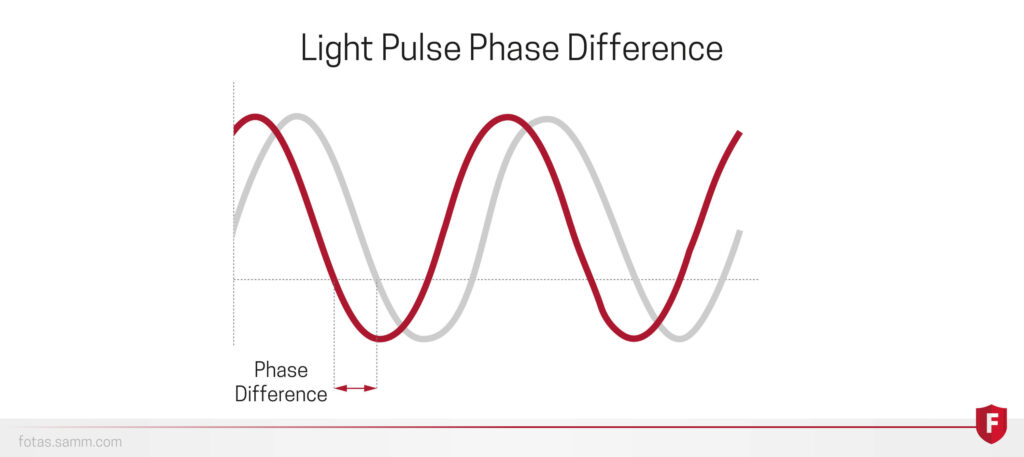
Photons in a laser share the same phase, direction and polarization. "Phase" comes from the Greek word for appearance, so a phase difference means one wave runs ahead of or behind another.
Equal phase concentrates energy — like combining many weak hammer blows into a single effective one. Phase equality is what allows Phase-OTDR and FOTAS to work.
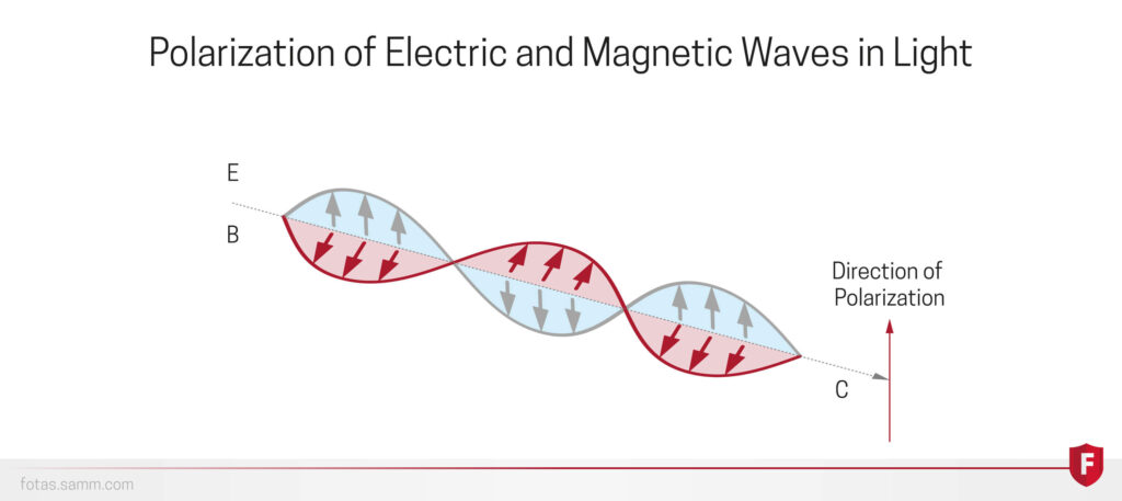
Polarization means the oscillations of a wave have a definite direction relative to its propagation. Electromagnetic waves are transverse waves whose electric and magnetic fields oscillate perpendicular to the direction of travel.
The direction of polarization is defined as parallel to the electric field. A familiar everyday example is 3D glasses, where rotating your head changes the perceived brightness.
Lasers work on the basis of stimulated emission. Atoms have quantized energy levels for their electrons — the levels exist at discrete values. Electrons tend to stay at lower levels, but when they absorb energy they move to higher ones.
Because higher energy levels are not energetically stable, electrons tend to emit that extra energy and fall back down. Most of the time this happens spontaneously, which is called spontaneous emission.
In a laser, this emission is controlled so that emissions become stimulated instead. When a photon is absorbed by an already excited electron, the electron emits two identical photons. Those photons are absorbed by other electrons, which emit many more — the basic working principle of the laser.
Distributed Acoustic Sensing (DAS) is a technology that detects acoustic signals. Force travelling through materials causes pressure displacements in the medium it passes through — air, earth, water and so on. These displacement phenomena are called acoustic waves, and sound waves are their most common example.
Single-point sensors detect signals at only one place, like the tip of a needle. In distributed sensors, by contrast, the sensing structure is continuous. FOTAS uses fiber optic cables for distributed acoustic sensing: light waves propagating in the cable are affected by acoustic waves, and the affected light is detected by devices such as Optical Time Domain Reflectometry (OTDR).
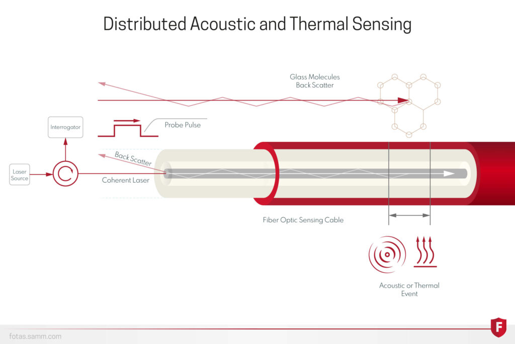
Distributed acoustic sensing refers to a system of optoelectronic products that perform real-time control and measurement through fiber optic cables extending across the targeted borders.
The most basic way to understand FOTAS technology is to imagine someone walking on a treadmill. As they move against the direction of the belt, sound waves spread around them. Someone at a certain distance can understand that a person is on the treadmill through real-time monitoring — even without being in the same room.
Throughout this process, acoustic signals are measured at every point along the fiber cable. Unlike sensors that measure at fixed determined points, the DAS system uses the cable itself as the sensor. In other words, a distributed acoustic sensor turns the fiber cable into microphones.
Detection happens only where a physical sensor has been placed.
The sensing structure is continuous along the entire installed fiber route.
Optical Time Domain Reflectometry is a measurement method used to characterize many features of fiber optic cables. It is mostly used to assess cable condition and locate problems: if there is any transmission-related issue in the fiber, an OTDR can find it.
The most common use is locating breaks. Fiber optic cables can carry data for roughly a hundred kilometers before amplification, so inspecting every point by hand would be practically impossible. There must be a device that examines the cable from afar — that is the purpose of OTDR.
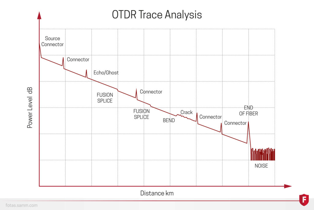
An OTDR sends light pulses into the fiber and measures the amplitude of the backscattered light. From the time difference it calculates fiber length, and from the amplitude loss it determines general losses, breaking points and other effects along the cable.
The amplitude of backscattered light always declines along the route because of impurities and light–particle interaction inside the fiber. From this decline the OTDR derives a loss coefficient — similar to electric current encountering resistance. This working principle reveals whether the fiber is broken or subject to any other loss-causing effect.
The further along the cable the measurement is taken, the weaker the scattered amplitude becomes. The device also records the time difference, so the location of a problem can be identified and diagnosed.
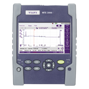
Two connection ports are located at the top of the unit: one for multi-mode fiber optic cables and one for single-mode cables. The cable must be connected to the correct port for valid measurements, as different cables may use different wavelengths.
Once the fiber is connected, the OTDR sends a laser pulse into the cable, the pulse travels and scatters backward, and the device measures the characteristics of that backscattered light.
Talk to the FOTAS engineering team about sensing distance, cable selection, route design, detection requirements and integration architecture.