


Integrity and Operational Risks
Product release, unexpected heating or cooling, insulation problems, thermal anomalies and abnormal operating conditions.

Distributed temperature and acoustic sensing for pipeline integrity monitoring, right-of-way security and external threat detection.
REQUEST A QUOTEPipelines cross long distances, remote terrain, environmentally sensitive areas and locations where access may be limited. Operators must monitor both pipeline condition and activity along the right-of-way.
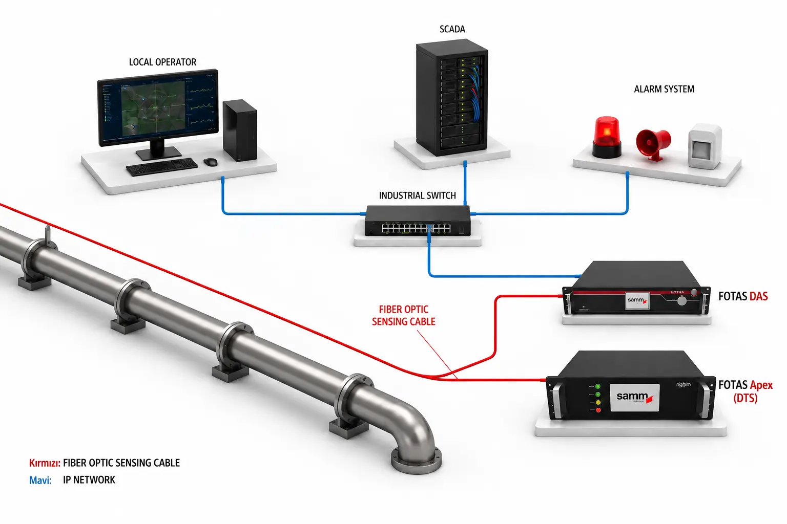
Fiber optic pipeline monitoring combines Distributed Temperature Sensing (DTS) and Distributed Acoustic Sensing (DAS). DTS provides distributed temperature information along the sensing route, while DAS monitors vibration and acoustic activity near the pipeline.
Together, the technologies can support integrity monitoring, third-party interference detection and pipeline corridor security without relying only on isolated measurement points.
Product release, unexpected heating or cooling, insulation problems, thermal anomalies and abnormal operating conditions.
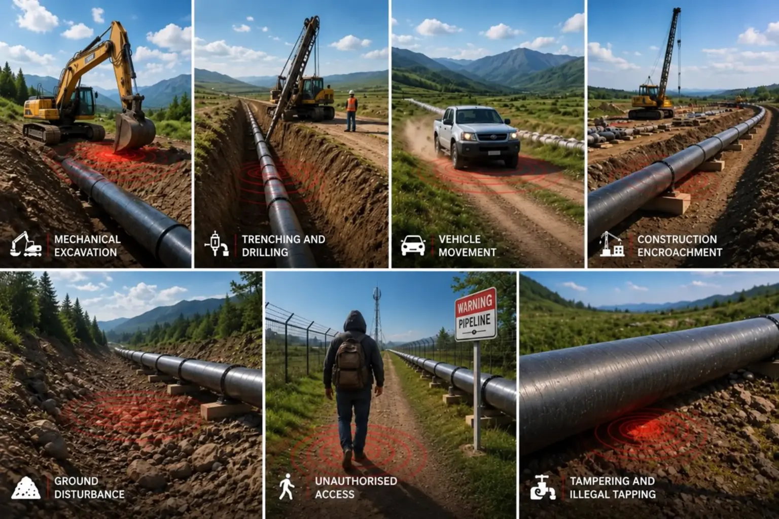
Unauthorized excavation, drilling, vehicle activity, encroachment, illegal tapping, vandalism and physical interference.
DTS and DAS use optical fiber as a distributed sensing medium, but they respond to different physical phenomena.
DTS uses optical fiber as a distributed temperature sensor. The interrogator analyzes Raman backscatter to calculate temperature at defined positions along the sensing cable.
DTS can support identification of:DAS uses optical fiber as a distributed vibration and acoustic sensor. The interrogator analyzes coherent Rayleigh backscatter to detect dynamic strain changes along the sensing route.
DAS can support detection of:
DAS provides a distributed monitoring layer for vibration and acoustic activity generated close to the pipeline route.
Depending on cable installation, site conditions and analytics configuration, event information can help operators identify the affected location and decide whether investigation is required.
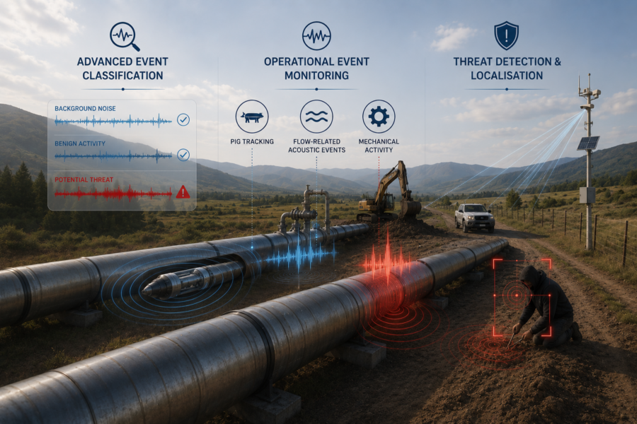
Detected vibration signatures can be assigned to configured event categories to support operator assessment and alarm management.
Classification performance depends on cable installation, acoustic coupling, environmental conditions, event signatures and system configuration.
Monitoring roles vary according to the transported medium, operating conditions, installation environment and expected event mechanisms.
| Pipeline Application | DTS Monitoring Role | DAS Monitoring Role |
|---|---|---|
| Gas Pipelines | Cooling or other thermal anomalies under suitable operating conditions | Excavation, drilling, vehicle activity and corridor interference |
| Liquid Hydrocarbon Pipelines | Leak-related temperature changes where thermal contrast develops | Third-party interference and right-of-way activity |
| Water and Wastewater Networks | Relevant thermal or operating anomalies | Excavation, construction and external activity |
| Chemical and Ammonia Pipelines | Thermal changes associated with product release or abnormal operation where measurable contrast develops | Corridor security and physical interference |
| District Heating and Cooling | Heat loss, insulation performance, hot spots and leak-related anomalies | Excavation and construction activity near the route |
Gas transmission lines, liquid hydrocarbon pipelines, water mains and district heating networks produce different thermal and acoustic responses. Alarm logic and sensing cable placement must reflect the specific asset.
The sensing cable may be installed alongside the pipeline, integrated with supporting infrastructure or routed along the right-of-way.
Applications can include buried pipelines, above-ground sections, cross-country transmission lines, gathering networks, pumping stations and block valve sites.
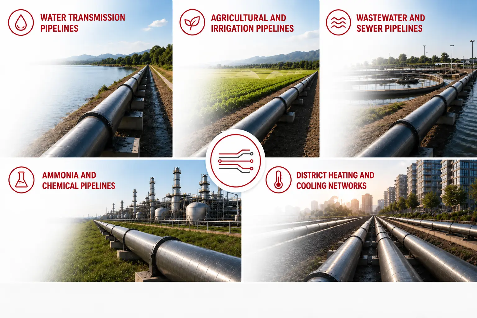
Distributed fiber optic sensing can also support water and wastewater networks, chemical pipelines, district heating and cooling systems, irrigation routes and multi-utility corridors.
Each network requires a monitoring strategy based on operating temperature, transported medium, credible failure mechanisms, installation conditions and response requirements.
FOTAS solutions can interface with SCADA, GIS, pipeline management systems, leak detection platforms, security monitoring systems and alarm management software.
The sensing system provides temperature, event and location information. Operational decisions and automated actions remain part of the approved project architecture and operating procedures.
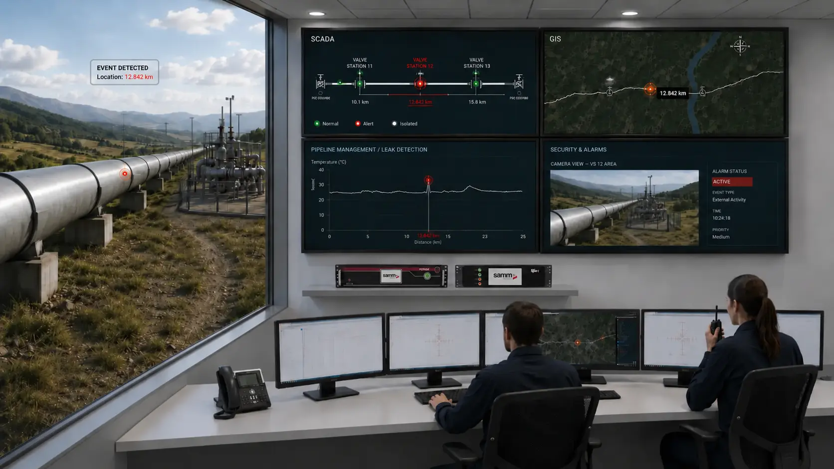
FOTAS combines DTS and DAS capabilities for pipeline integrity monitoring and right-of-way security. DTS provides distributed temperature information for relevant thermal anomalies and operating conditions. DAS provides vibration and acoustic event monitoring for third-party interference and external activity.
Continuous thermal information along the installed sensing route rather than isolated measurement points.
Distributed vibration and acoustic monitoring across the pipeline corridor.
Identify the affected position along the route to support targeted investigation.
The sensing cable requires no electrical power along the monitored pipeline.
Connect measurement and event information to SCADA, GIS and pipeline management platforms.
Configuration based on pipeline type, risk environment and verified project requirements.
The final configuration should be based on pipeline type, risk environment, sensing cable installation, required interfaces and verified product performance.
Evaluate pipeline risks, sensing cable deployment, monitoring zones and system integration with the FOTAS engineering team.